The Missing Link
1- Senior resident, 2- Assistant Professor, 3- Professor;
Department of Pulmonary and critical care medicine, ESI PGIMSR, New Delhi, India
*Corresponding author, mail id- diptigothi@gmail.com
Case
A 55 year old man with chronic obstructive pulmonary disease (COPD) was admitted for an infective exacerbation with hypercapnic respiratory failure. He was initially managed with non-invasive ventilatory support. He had to be intubated after one hour due to lack of improvement. The patient was put on invasive mechanical ventilation in the Assist Control-Volume Control. On the 5 th day of mechanical ventilation, the patient improved gradually and was planned for weaning. But there were some sudden changes in the ventilator graphs due to which the weaning criteria were not satisfied (Video 1). The ventilator settings at that time were Assist Control-Volume Control mode; FIO2 24%; TV 320 ml, Set Rate 18, PEEP 6cm H20, decelerating flow waveform at 60 litres/minute. The volume-time (VT) scalar, flow-time (FT) scalar, pressure-volume (PV) loop and flow-volume (FV) loop are shown in video 1.

Video 1: Ventilator waveform changes observed in our patient
Question
What do the ventilator waveforms indicate?
- Auto PEEP
- Double triggering
- Leakage in the ventilator circuit
- Secretions in the ventilator circuit
C. Leakage in the ventilator circuit.
Discussion
Air leak in mechanically ventilated is a major problem in clinical practice contributing to the ineffectiveness of assisted ventilation. The leakage can be from any part of the circuit. The identification of a leak from the ventilator circuit requires constant monitoring of the ventilatory parameters and graphs. The expiratory tidal volume (Vte) becomes less than the inspiratory tidal volume (Vti) as a consequence of air leak. In our patient the Vti was 320ml and the Vte had suddenly dropped to 190 ml raising suspicion for an air leak. The volume-time (VT) scalar showed that the expiratory limb was not returning to baseline (video 1).
AutoPEEP also shows changes similar to air leak in the VT scalar and hence can be confused with air leak. AutoPEEP, also known as intrinsic PEEP occurs due to air trapping and over-distension. This is usually due to an insufficient expiratory time. The identification and differentiation of auto-PEEP and air leak is important as both interfere with weaning from mechanical ventilation and their management is different. The changes in various ventilator graphs in the presence of leak and auto PEEP have been compared in figure 1.
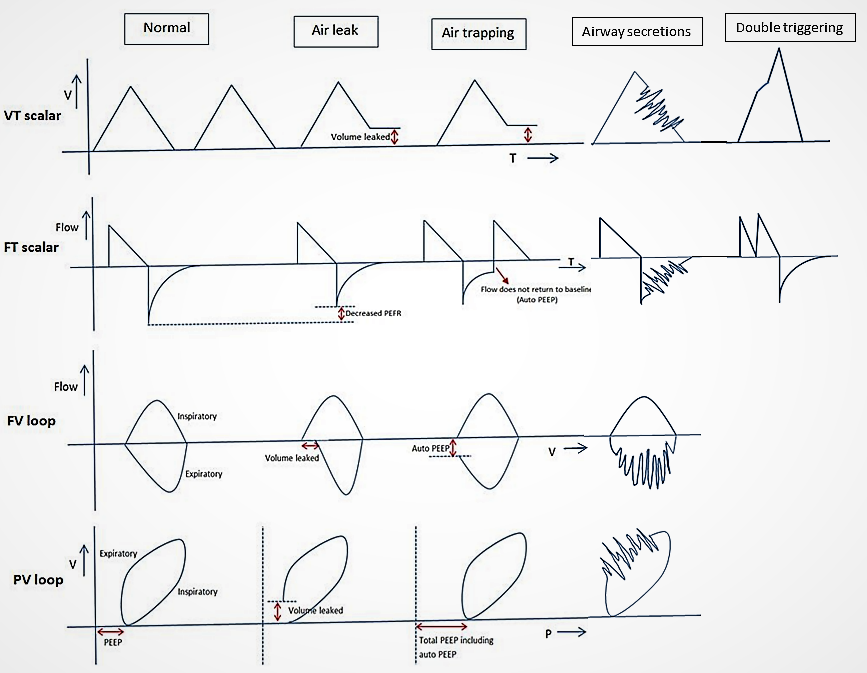
Figure 1: Ventilator waveform patterns in assist control/volume control mode in decelerating ramp in presence of air leak, autoPEEP, airway secretions and double triggering.
In the VT scalar the expiratory limb does not return to baseline (red coloured double arrow) in both air leak and auto PEEP. The differentiation of air leak and auto PEEP on FT scalar requires minute observation. In presence of air leak on the FT scalar, the peak expiratory flow rate is reduced, thus diminishing the overall size of the expiratory graph. In presence of auto PEEP, the expiratory flow does not return to baseline on the FT scalar (red arrow). The FV loop is ideal for differentiating the air leak from auto PEEP. Air leak is characterised by the lack of return of the expiratory limb of FV loop to baseline along the volume axis (i.e., the x-axis). But in auto PEEP, the expiratory limb does not return to baseline along the flow axis (i.e., the y-axis) and another breath is started. In the PV loop, the presence of air leak can be detected when the expiratory limb does not return to baseline. The auto PEEP in PV loop can be identified from the shift of the loop to right on the x axis (answer choice A is incorrect).
The changes in the ventilator graphs associated with double triggering and secretions in the circuit have also been shown in figure 1. Double triggering is characterised by two inspirations occurring in succession in a single respiratory cycle (answer choice B is incorrect) whereas the presence of airway secretions can cause a saw-tooth pattern in the expiratory limb of the flow-time curve (answer choice D is incorrect).
In our patient, when the ventilator waveforms suggested presence of air leak, the whole circuit was checked. The leak was due to a crack in the water trap of the inspiratory limb of the circuit (figure 2).
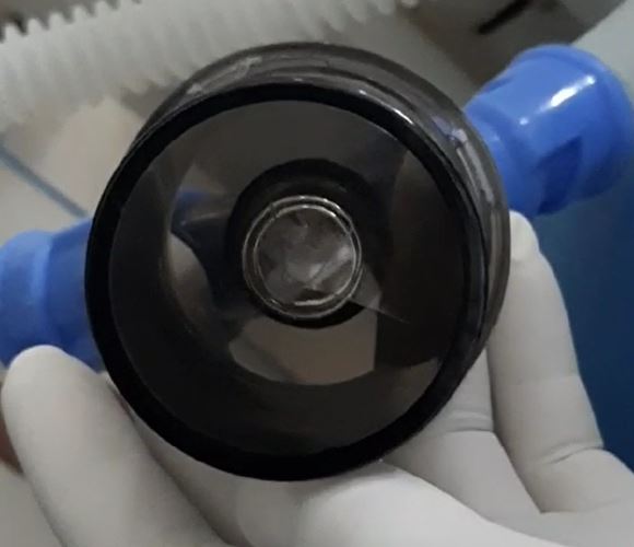
Figure 2: Crack in the water trap of the inspiratory limb of the ventilator circuit.
After the inspiratory circuit was replaced with a new one, there was no further leak. The patient was successfully weaned off ventilatory support and was extubated the next day.
References
-
Emrath, E. The Basics of Ventilator Waveforms. Curr Pediatr Rep. 2021;9:11-9. https://doi.org/10.1007/s40124-020-00235-4 .
-
Online reference. Last cited on 10 December 2021. Available from https://derangedphysiology.com/main/cicm-primary-exam/required-reading/respiratory-system/Chapter%20551/introduction-ventilator-waveform
-
Prabhakaran P, Sasser WC, Kalra Y, Rutledge C, Tofil NM. Ventilator graphics. Minerva Pediatr. 2016;68(6):456–69 Good review of ventilator graphics in pediatric patients.
-
Dexter AM, Clark K. Ventilator graphics: scalars, loops, & secondary measures. Respir Care. 2020;65(6):739–59.